5 Steps for More Effective Hydraulic Troubleshooting
Tags: hydraulics
Have you ever been asked to troubleshoot a hydraulic issue? Whether you are a maintenance person, salesman, service provider or consultant, you should follow the same guidelines when diagnosing and fixing the problem.
What happens in many plants is that troubleshooting is done by a parts-changing process, which can be expensive in downtime and part costs. Plus, when the machine finally becomes operational, no one has learned anything because so many random things were done. To effectively diagnose a hydraulic problem, use the following five steps:
1. Identify the Problem
Most hydraulic issues can be divided into two categories: pressure or volume. A pressure issue is one where the pressure won’t build high enough to operate the machine properly.
For example, a press may require 3,000 pounds per square inch (psi) to machine a part or compress a board, but the pressure only builds to 2,000 psi. If the issue is speed related, then a volume problem is most likely occurring. This means that either the pump is not delivering the required amount of oil or there is bypassing somewhere in the system.
A maintenance manager at a plywood plant recently called and wanted to talk about a hydraulic problem on his lathe. After being asked a few key questions, he admitted that he didn’t really know what the problem was.
“Let me go talk to the crew and get more information,” he said.
It’s hard to fix something if you don’t know what the problem is.
The most difficult hydraulic issues to solve are those that happen intermittently. In one case, a hydraulic motor would stop rotating for a few seconds but wouldn’t do it all the time. Several hours went by before the motor did it again.
When the hydraulic and electrical systems were checked, everything appeared normal while operating. The electrical cabinet just happened to be open during one stoppage, and a red light illuminated on the amplifier card for a few seconds and then went off.
The red light indicated the power supply voltage had dropped below 21 volts. After much research, a loose wire was found in the cabinet. The intermittent stopping of the motor was a volume problem. When the power supply voltage dropped below the acceptable level, the pump was de-stroked to a zero flow output.
2. Gather Information
Once you’ve identified the type of problem, the next step is to gather information. More than likely when you arrive at the problematic hydraulic system, some things have already been done. Have any pressure or electrical adjustments been made? Have any hydraulic components been changed out?
If so, do the new components have the exact part number as the components that were replaced? One number or letter difference in the part number may mean that the valve will not work in the system.
Several years ago, a positioning problem was identified on an oriented strand-board press in Georgia. The position of the platen was controlled at four different points with linear-displacement transducers. The pressure in the ram that controlled one of the corner rams was fluctuating excessively.
After 11 hours, it was determined that the replacement position-control valve had one letter different than the original valve. Once the correct valve was installed, the press operated normally.
Visual checks must be made during this process to assess the oil level, filter condition, leakage, pump coupling condition, etc. Also, ask for the latest oil analysis report to verify the oil’s cleanliness level.
I was recently called to troubleshoot an issue at an automotive plant where five pumps had been changed in 24 hours. When I arrived, I asked if anything had been done prior to the repeated failure of the pumps. The supervisor said that a hose failed in the system and that the reservoir was refilled with fluid during the shift change.
Shortly after that, the issues with the pumps started. After inspecting the system, I did not see a breather cap on the reservoir. Apparently, when the first-shift oiler refilled the tank, he did so by removing the breather cap.
Once filling was completed, the second-shift oiler installed a pipe plug on the threads where the breather was originally mounted. Now there was no place for air to enter the reservoir, which resulted in the failure of the pumps.
Machine operators can provide some of the best information as to what is occurring. While maintenance workers may only show up when a machine malfunctions, the operator knows how the machine feels, sounds and runs. This individual usually has data displayed on a screen and understands when a pressure, position or other indicator is reading incorrectly.

A blown fuse on a solenoid-operated valve resulted in
unnecessary downtime at a plant in Arkansas.

Reading a hydraulic schematic can identify a
problem before the first part is replaced.
3. Review the Schematic
The best times you will spend troubleshooting is while reading and tracing a hydraulic schematic. Frequently, valves are inside manifolds or located in out-of-the-way places. By following the lines on the schematic, you can often find the problem before the first part is changed out.
Several years ago, I was flown to a plant in Arkansas that was having speed issues with a large stacker. The stacker was supposed to operate at fast and slow speeds. The problem was that it only operated in the slow mode of operation. When I arrived, several millwrights, electricians, supervisors and the plant manager were near the machine.
I asked for a hydraulic schematic of the system. One millwright said, “We never use those because they’re locked up in the plant engineer’s office.” I told him that this was one time we were going to need it because several of the valves were located on and inside a manifold.
Once the schematic was found, I identified one solenoid-operated valve that had to be energized in order for the stacker to lower. When the valve was manually actuated during the fast cycle, the stacker lowered quickly. The issue was a blown fuse on the solenoid-operated valve. The plant could have saved hours of downtime had it taken the time to troubleshoot from the schematic when the machine first went down.

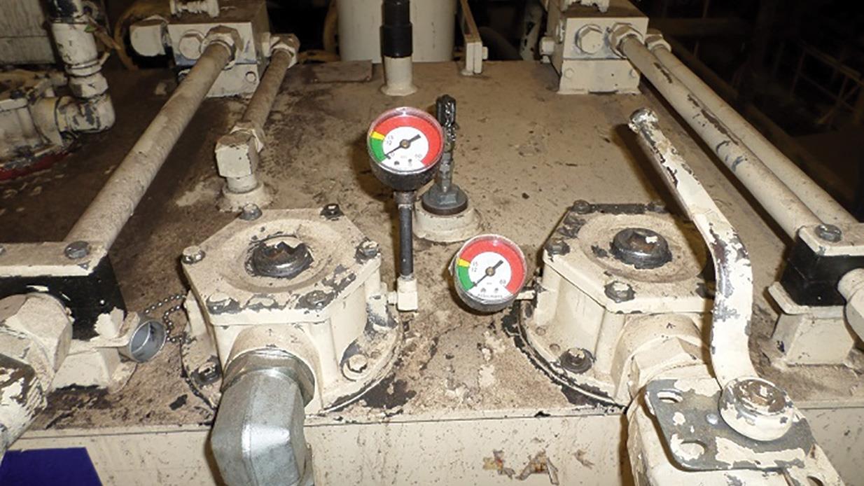
It is important to verify that
all system pressures are set properly.
4. System Troubleshooting and Adjustments
After you have identified the problem, gathered information and reviewed the schematic, you should verify that the system pressures are set properly. This includes the pump compensator, relief valve, pressure-reducing valves and other pressure-control valves in the system. Also, ensure that all the accumulators are pre-charged with dry nitrogen. Many times an issue can be resolved by simply setting the pressures to the appropriate level.
After one of my courses in Oregon a few years ago, a student asked me to look at a system that was running extremely hot. He wasn’t exaggerating, because when the reservoir was photographed with an infrared camera, it revealed a temperature of 320 degrees F.
I checked the tank line of the relief valve, which should have been at ambient temperature. However, I found a temperature of 340 degrees F. This indicated that the relief valve was stuck open or set below the compensator setting or that the pump’s compensator spool was stuck. When the relief valve was set 250 psi above the compensator, almost immediately the temperature started dropping.
Another issue detected in this system was that the accumulator manual dump valve was partially open, allowing oil to flow to the tank, generating heat. Twenty-four hours after the pressures were set and the dump valve was closed, the temperature dropped to 132 degrees F.
Once the pressures are set, make temperature checks throughout the system to confirm that no excessive bypassing is occurring. This can be done with an infrared camera or temperature gun. Typically, there are several tank lines in a hydraulic system that should be at ambient temperature. These include manual and automatic accumulator dump valves, air bleed valves and relief valves used with pressure-compensating pumps.
The suction line and case drain of a variable displacement pump should also be checked for excessive heat generation. It is important to record the temperature of the lines when the system is operating normally to establish a reference.

Use an infrared camera to check accumulators.

Check the accumulators used for volume with an infrared camera. When cycling frequently, the bottom half or two-thirds of the shell should be hotter than the top half or one-third. The pre-charge pressure should be checked with a charging rig for accumulators that do not cycle regularly or that are used for shock and to maintain pressure.
The key to troubleshooting pressure problems is to isolate various points in the system. Oil will always take the path of least resistance. If the machine is experiencing a pressure problem, then oil is most likely bypassing in the system.

A valve that was stuck open proved to be an
issue in an injection-molding machine that
would not rotate at the proper speed.
Recently, a plywood plant was only building 1,400 psi in its prepress rams when 2,100 psi was required. The line to each ram was photographed with an infrared camera. The line to one ram was 142 degrees F, while the lines to the other three rams were 120 degrees. F. A manual valve was installed in the line to the ram that was hot.
When the manual valve was closed, the pressure built up to the normal level of 2,100 psi. The problem was the prefill valve for that ram was stuck open, allowing all the pump volume to bypass back to the tank at 1,400 psi.
Many times a valve that is stuck open can be removed from the system to check for wear and contamination. A few months ago, the extruder motor on an injection-molding machine would not rotate at the proper speed. This indicated a volume problem in the system.
Several tests were conducted, including installing flow meters to check the pump volume and inserting mechanical stops in the manifold valves to prevent them from opening. When removing one logic valve to install the mechanical stop, the valve was found to be stuck open. This valve was teed off the line to the hydraulic motor, which allowed the oil to bypass back to the tank.

Installing a manual valve in the line to a
prepress ram helped troubleshoot a pressure
problem at a plywood plant.
5. Reliability Checklist
When the issue is solved, the toolboxes are loaded up and everyone usually goes back to their normal duties. What should be done at some point in the near future is to develop a reliability checklist on the system.
This list should consist of pressure and temperature readings, filter and breather conditions, oil cleanliness, condition of the hoses and clamps, current readings on the electric motor, voltages to proportional valves, etc. These checks should be made regularly to avoid unscheduled downtime. The recorded information will be a useful tool when future hydraulic issues occur.
When a machine goes down, panic management frequently kicks in and parts start being changed. Often times the problem can be very simple. Several years ago, a press was down for five days because of an O-ring stuck in the drain line of a pressure-control valve.
Hydraulic troubleshooting is a step-by-step process. By following the five steps in this article, you can become a hydraulic troubleshooter and not simply a parts changer.