How to Identify and Control Lubricant Contamination
Many people are aware that lubricant contaminants cause wear in machines, but all too often that knowledge does not translate into action. It is surprisingly common for plants to go to great lengths in monitoring the condition of their equipment and their lubricants, but to do very little to address the problems that are uncovered.
Sometimes inaction is due to larger issues in the plant—perhaps a lack of understanding of oil analysis reports or simply a lack of proper contamination control equipment. These same issues can also crop up in other areas of condition monitoring, but the focus of this article is to show how oil analysis—along with the right breather and filtration equipment—can be used to help identify and ultimately control solid particle contamination.
The Appearance of Particle Contamination … Now What?
Contaminants are certainly easier to detect than they are to control. As modern lubrication has advanced, many users have become aware of the effects of particle contamination on lubricated machinery.
A multi-industry study published by the National Research Council of Canada showed that particle contamination was the root cause of 82 percent of wear-related failures.
Based on this information, it stands to reason that controlling and monitoring particle contamination should be a primary goal of any lubrication program. However, simply identifying contamination control as a goal and monitoring the levels of contamination in machines will not extend their lifespan.
With the right combination of training and equipment—including proper filtration and breathers—you can make a plan to tackle contamination control in a cost-effective and practical way.
How to Start Controlling Contaminants
Your primary tool in understanding and measuring contamination is oil analysis. To maximize the value of oil analysis efforts, especially those focusing on particle count, several processes should be implemented:
The first step is to set targets or limits. To establish the allowable particle count for a given machine, an ideal value must be determined based on what can reasonably be achieved through cost-conscious measures.
If the goal is not achievable, it has little value in guiding decisions. Condition monitoring tools should be used to target problems and focus efforts where they will yield the greatest return. If all particle counts are high, there can really be no focus.The second step is to employ the appropriate methods to achieve the identified goals. Particle contamination control has several components, but it begins with good lubricant storage, handlingand applicationmethods and extends to choosing the right equipment for controlling contamination.
There are a range of equipment options for your machines. Two of the most popular and effective are better filters and better headspace breathers. Let’s take a look at filtration first.
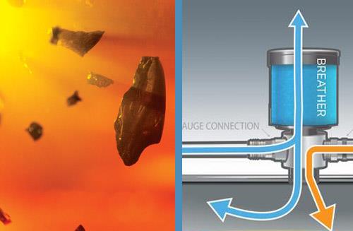
How to Choose a Desiccant Breather that Fits Your Application
Desiccant breathers are great contamination control accessories for machines that would otherwise be breathing in dirty, wet air. These devices allow for the air being ingressed by the machine to be cleaned of particulate matter and also dried to help control the amount of water in the oil. This becomes very important in critical machinery as well as those that are in harsh environments where the oil may become contaminated and break down quickly.
These breathers have a particulate filter phase and a moisture absorption phase. Both of these phases are essential not only for the health of the lubricant but also for the health of the machinery. Solid particulate contaminants can lead to machinery failure mechanisms such as three-body abrasive wear. Moisture contamination can result in adhesive failure mechanisms and increase the rate at which lubricants break down.
Oil by nature is hygroscopic, which means it will absorb moisture readily from any source, including from humidity in the air. By utilizing a desiccant breather, you can reduce the amount of moisture in the air that is entering the system.

The headspace is important to keep in mind, as it can help determine the amount of “breathing” that will occur inside the machine. Therefore, it is imperative to understand how much the headspace can fluctuate. For instance, the headspace in a splash-lubricated gearbox will fluctuate less than that of a hydraulic system reservoir where there are large volumetric changes within the sump. This volumetric flow rate must be within the breather’s capabilities, or it may cause a vacuum or pressurization condition inside the component.
The environment in which the machine operates should be considered as well. For severe environments, such as those with water spray and large amounts of dirt, select a desiccant breather that can handle the expected amounts of contamination. For the most severe environments, you might choose a breather with a check valve or quick exhaust manifold so the detrained air does not pass back through the desiccant, prolonging the desiccant’s life.
The cleanliness level required by the machine must also be taken into account when determining the desired desiccant quality. Of course, the more critical machines should receive the most attention. There are quite a few breather options out there, and many different sizing considerations for each one. Always tell your supplier as much about your application and environment as possible to ensure that the right option is recommended.
Considering all of these variables will provide the most effective way to select a desiccant breather. While a number of options are available, some are better suited for certain situations. Remember, it is far better to provide more protection than needed rather than to skimp on quality in order to save money.
You may think that filtration starts after a lubricant has seen use in a machine, but in fact the truth is often ignored that “new” oil is not necessarily clean oil.
New Oil Doesn’t Always Mean Clean Oil
New oil is actually a common source of particle contamination because it is typically dirty upon arrival. In the average plant, new oil is often further contaminated by being dispensed into a dirty container with unsanitary transfer equipment and finally applied to the machine through a soiled funnel.
By properly storing, filtering and applying new lubricants, along with the use of simple contamination exclusion methods such as high-quality breathers and seals, an appropriate level of cleanliness can often be maintained for even nonfiltered systems. When these exclusion methods are insufficient, methods to remove contaminants must be used.
Contamination removal techniques include portable filtration, permanently mounted off-line filtration and upgrading active system filters to best possible level of performance for a given system. Of course, it is more cost-effective to practice good contamination exclusion methods, and therefore exclusion should be the first method considered.
How to Choose the Right Filter for Controlling Contamination
While oil contamination takes many forms, the following three classifications cover the majority of industrial problems:
- Dirt - Dust and solid contaminants creep in from the surrounding atmosphere. Contaminants could include metal chips from machining, rust and wear products from seals, bearings and gears, core sand from castings, weld spatter from welding, paint flakes from painted surfaces and soot from diesel engines.
- Water - The most troublesome sources are often condensation, cooler leaks, gland leakage and seal leakage.
- Sludge - This forms primarily as a result of oxidation of the oil itself, especially at high temperatures. Accumulation of fine particles may also fill clearance spaces by silting, resulting in erratic operation and sticking of hydraulic system valves and variable flow pumps.
Different filtration specifications are required for each of these contaminants. With particulates, the maximum particle size should be kept below the minimum thickness of the fluid film. Table 1 gives typical ranges of film thickness requirements for industrial system components.

Table 1. Typical Minimum Fluid Film Thickness
With water, any free moisture may promote both rust and sludge by reacting with oil additives and metal surfaces. The critical limit of free water in the lubricant is the amount that causes the fluid film to fail in the load zone.
Filter Performance Factors
Before selecting an appropriate filter, the following must be examined:
- Demands Imposed by Machinery Components - oil viscosity at the operating temperature, oil feed rate and permissible pressure drop.
- Expected Size, Type and Level of Contaminants - the ingression and formation rate of environmental dust, metal chips, fly ash, wear particles, water, and/or other contaminants.
Many oil filtration units involve small cartridges with flow capacities up to three to five gallons per minute (gpm). To increase the allowable flow rates, a system of smaller cartridges is arranged into a filtration unit. The following factors provide guidelines for selecting these filter units and possible alternatives.
Particle Size. Film thickness data in Table 1 represents the approximate filtration levels that would sustain the optimal protection from particles. Smaller particles will freely pass through the load zone, but wear accelerates as their size approaches or exceeds the minimum film thickness.
In ball and rolling element bearings where elastohydrodynamic lubrication prevails, larger abrasive contaminants tend to cause surface damage in the form of microspalls accompanied by shortened fatigue life.
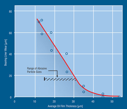
Figure 1. Increase in Journal Bearing Wear as Particle Size Exceeds the Minimum Film Thickness (Broeder and Heijnkemp)

Table 2. Typical Filtration in Circulating Oil Systems
In general, a filter selected with a nominal rating to match these requirements will remove the majority of larger particles. It must be kept in mind, however, that too fine of a filter may be undesirable because of the possibility of clogging, which requires frequent maintenance. Also, because of the large pressure drop across a filter, the power losses could become excessive if care is not taken to select the right filtration option.
The Verdict
In the end, if you are focused on eliminating contaminants in your oil and reducing the amount of wear on your lubricated assets, proper filtration and carefully chosen headspace breathers (ideally with desiccant or other contamination control features) can help. Combine these tools with the proper training, and you have a winning formula for sustainable (and ultimately profitable) contamination control.
References:
1. J.J. Broeder and, J.W. Heijnkemp. "Abrasive Wear of Journal Bearings by Particles in the Oil (Apparatus, Experiments and Observation)." proceedings of Mechanical Engineers, London, V. 180, p. 35-40, 1965-66.
2. J.K. Duchowski. "Examination of Journal Bearing Filtration Requirements." Lubrication Engineering, September 1998. p. 18-28.
3. H. Amirkhanian. "Advances in Centrifugal Filtration." Machinery Lubrication, July-August 2004. p. 34-36.
4. Y. El-Ibiary. "Extending Bearing Life and Performance." Machinery Lubrication, July-August 2004. p. 46-47.
5. H.J. Parkhurst. "Filter Element Service Life Evaluation and Optimization in Paper Machine Lubrication Systems." Lubrication Engineering, October 1994. p. 760-764.
6. M.M. Khonsari and E.R. Booser. Applied Tribology-Bearing Design and Lubrication, John Wiley & Sons, 2001.
7. M.M. Khonsari and E.R. Booser. "Effect of Contamination on the Performance of Hydrodynamic Bearings." Journal of Engineering Tribology, Proceedings of the IMechE, Part J, August 2006. p. 419-428.