
.jpeg)


In an ideal world, multiple components could be produced in a single piece, or coupled and installed in perfect alignment. However, in the real world, separate components must be brought together and connected onsite. Couplings are required to transmit rotational forces (torque) between two lengths of shaft, and despite the most rigorous attempts, alignment is never perfect.
To maximize the life of components such as bearings and shafts, flexibility must be built in to absorb the residual misalignment that remains after all possible adjustments are made. Proper lubrication of couplings is critical to their performance.
Misalignment
Misalignment can occur as either an offset or as an angular displacement on two of the possible three axes (Figure 1). The third axis, in the longitudinal direction, is not commonly measured, though errors in this direction can result in constant excessive thrust loads in a system.

Figure 1. Types of Misalignment
For major installations, such as large compressors, wire alignment methods are used. Smaller applications have traditionally used rim and face dial indicator readings to quantify and correct misalignment, though optical laser indicators are rapidly gaining in popularity due to their ease of use and accuracy.
In pace-setting maintenance organizations, efforts are also made to compensate for thermal growth that occurs in equipment during operation. All materials (except water) expand a small amount when heated, the amount by which they do so is governed by the material’s coefficient of thermal expansion and the degree to which it is heated. A machine that is brought into alignment at ambient temperature will creep into a position of misalignment as the machinery materials climb or fall to operating temperature.
Attempts are made to preheat or cool equipment to normal operating conditions before performing alignment checks. Alternatively, calculations of anticipated thermal growth can be used to intentionally misalign the drive train at ambient temperature so that it may grow into alignment.
Whatever precautions are taken to make alignments as precise as possible some amount of residual misalignment will inevitably remain. Misalignment forces rigid machine components such as shafts to deflect in order to effectively become aligned.
This deflection stresses the components, causes vibrations, and distributes higher and uneven loads on the structures that support these elements, such as bearings. These stresses waste energy and can dramatically reduce equipment life and reliability.
Designed properly, couplings can absorb misalignment forces so that more expensive, critical and sensitive components may be saved. While rotating shafts appear sturdy, the bearings which support them are some of the most sensitive precision components in the drive train.
Types of Couplings
Coupling designs may be divided into four principal categories, each having several specific designs. Solid and magnetic couplings do not require lubrication, but are included here for completeness. Solid couplings are fundamentally rigid structures that do not compensate for misalignment, but do allow two shafts to be joined for the purpose of transmitting torque.
Bolted hubs keyed onto shafts are a common example of a machine with magnetic couplings. Magnetic couplings allow shafts not in direct contact to be driven together using powerful permanent or electrical magnets. A sealless magnetic drive pump is a common example.
There are some conventional applications that could be fitted with a stand-alone magnetic coupling using this same principle and ultra-powerful (and expensive) permanent magnets.
Other coupling types are flexible couplings and fluid couplings. Many flexible couplings use fixed position flexible metallic, rubber or plastic elements, such as discs or bushings, that rotate with the shafts and absorb misalignment. Designs of this type do not require lubrication.
Others such as geared, chain, grid and universal joints do require lubrication for proper performance and longevity. Fluid couplings include torque converters and torque multipliers as well as comparatively simple fluid couplings, which are couplings filled with lubricating fluids that rely on the fluid itself to transmit torque.
Flexible Couplings
Gear couplings (Figure 2) compensate for misalignment via the clearance between gear teeth.

Figure 2. Gear Couplings
Shaft-mounted external gear teeth on both shafts mate with internal gear teeth on a housing that contains a lubricant. Other designs mount external teeth on only one shaft, mating with internal teeth mounted to the other shaft.
Acceleration or deceleration can result in impacts between gear teeth due to backlash from the clearance being taken up on opposite sides of gear teeth. Misalignment will result in sliding relative motion across mating teeth as they pass through each revolution.
Chain couplings (Figure 3) operate similarly to gear couplings. Sprockets on each shaft end are connected by a roller chain.
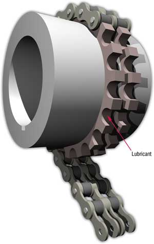
Figure 3. Chain Couplings
The clearance between its components as well as the clearance in mating the chain to the sprockets compensate for the misalignment. Loading is similar to that of geared couplings.
External grid couplings (Figure 4) use a corrugated steel grid that bends to compensate for loading induced by misalignment.

Figure 4. Grid Coupling
Grooved discs attached to the ends of each shaft house the grid, which transmits torque between them. Low amplitude sliding motion develops between the grid and grooves as the grid deforms under load, widening in some locations and narrowing in others over each revolution.
Universal joints are used for maximum allowable misalignment up to 20 to 30 degrees, depending upon the specific design. They are used extensively for the drive shafts of vehicles to allow the wheels to move with the suspension system. Universal joints use a four-spindled component called the spider to connect two shafts terminating in yokes or knuckles at right angles (Figure 5).

Figure 5. Universal Joint
Each of the four spider journals is supported by a bearing or bushing contained in one of the knuckles, which allow articulation. In some cases, greater articulation can decrease wear rates by allowing more complete development of a lubricating film.
Lubricants for Flexible Couplings
Both lubricating oils and greases can be selected to lubricate flexible couplings. Unless specifically noted by the coupling designer, couplings for the majority of industrial components are grease lubricated. Coupling components are protected primarily by an oil film which bleeds from the grease thickener and seeps into the loading zone.
Lubricated flexible couplings require protection from the low amplitude relative motion that develops between their components. Other concerns include centrifugal stress on the lubricant (particularly grease), which causes premature separation of the oil from the thickener, poor oil distribution within the housing and oil leakage from the housing.
The motion’s low amplitude, articulation speed, and tendency toward a sliding rather than rolling action inhibits the development of hydrodynamic (full-film) lubrication. Greases made with high-viscosity base oils, antiscuff (EP) and metal-wetting agents are recommended to overcome the boundary (mixed film) conditions that often exist in flexible couplings. High oil viscosity also slows the leakage rates.
Centrifugal forces in flexible couplings can be extreme, becoming greater as distance from the rotational axis is increased. Even moderately sized couplings can generate forces thousands of times greater than gravity (referred to as Gs). Grease manufacturers place a high priority on formulations that resist premature separation of oil and thickener due to the high G forces.
Fluid Couplings
Fluid couplings transfer momentum from the input shaft to a fluid and then to the output shaft when transmitting torque. Misalignment is accommodated solely by clearances between the moving parts. The small clearances don’t provide much room for error in alignment. However, it is possible to effectively compensate for shock loading and high torque starting loads, as there is no solid connection between input and output shafts.
In fluid couplings, an impeller attached to the input shaft accelerates fluid within the coupling as it spins, much like in a centrifugal pump. This fluid then hits the vanes of the output shaft’s runner, transferring its momentum as the runner accelerates. It will accelerate until it approaches the speed of the input shaft, but will never actually reach it.
The difference in speed between the input and output shafts is known as slippage. Of course, frictional and viscous drag must be overcome before the output shaft can rotate. The minimum input speed required for this condition is known as the stall speed. Equipment with large static loads, such as a steam or gas turbine, would incorporate a fluid coupling to minimize the initial stress on the driving shaft.
Shock loads on the input side, such as starting torque, are never created. The speed of the input shaft is never restrained. When the stall speed is exceeded, the output shaft will begin to accelerate, but will do so at a constrained rate due to its moment of inertia (resistance to angular acceleration).
Slippage is created as the runner accelerates to the speed of the input, dissipating excess energy through viscous heat generation in the fluid. Output side shock loads will be similarly dissipated, even if the output shaft should completely stall.
Torque converters and multipliers are special applications of fluid couplings that allow the input torque to be modified before transmission. These designs operate fundamentally by the same principles, but are mechanically much more complex. A detailed discussion of these devices is outside the scope of this article.
Lubricants for Fluid Couplings
The dissipation of energy that makes fluid couplings so tolerant of shock loading creates the potential for rapid and extreme increases in fluid temperature. The energy dissipated during stall and slip is converted to heat through the viscous shearing of the fluid (fluid internal friction).
In extreme applications, such as a torque converter in an automobile climbing a steep hill or pulling a heavy load, the fluid temperature can rise substantially above the normal 200°F operating temperature in less than a minute.
Oxidation and thermal degradation resistance are important qualities of oil used for fluid couplings because of the potential for drastic temperature increases. Similarly, a high viscosity index (VI) is also useful to prevent severe decreases in operating viscosity at temperature spikes and excessively high operating viscosity at low temperature conditions.
Low viscosity fluids are ordinarily used in these applications to reduce the power lost to heat due to fluid friction. Fluid coupling viscosities may fall between 2.5 to 72 cSt at 40°C. For fluid couplings designed to operate at high temperatures, such as in automobile ATF applications, viscosity limits may be given at 100°C. Typical automotive ATF requirements would be 3 to 7 cSt at 100°C.
These fluids must also resist foaming due to the severe agitation caused by the impeller’s movement and its impact upon the runner vanes. Rust protective properties help preserve the coupling’s metal components. Hydrocarbon-based fluids are superior in this regard to other fluids, but their performance can be further improved through rust inhibiting additives. Seal compatibility is also important for long-life usefulness.
Maintenance Recommendations
Acceptable life can be expected from any of these devices only if proper maintenance is performed. Lubricant levels and quality must be verified through periodic checks. Additional lubricant may need to be added to compensate for leakage, and periodically the lubricant must be flushed and changed to remove harmful byproducts of lubricant breakdown, to replace oil-depleted grease or to refresh the additive population.
Gear couplings require perhaps the most maintenance. Typical relubrication intervals are six months to one year, depending upon application severity and experience.
All maintenance tasks must be performed with attention paid to contamination control. The sliding contact suffered by many couplings indicates that abrasive three-body wear caused by particulate contamination could be particularly damaging. Improper removal of solvents used to clean couplings during inspections and flushing operations can lead to significant viscous thinning of the lubricant in operation, or detrimental reactions with grease-thickening materials.
All couplings will endure significantly better when the demands placed on them are reduced. Consider the first line of defense to be a minimization of shock loading, including hard starts and sudden load reversals. Sometimes operational demands make this impossible. The principal source of loading in coupling systems can be controlled to a great extent, however. Proper alignment is considered a high-priority, precision maintenance functions.
Use vibration analysis or thermography during operation to identify couplings that are not in alignment, as even the sturdiest foundations shift over time. Certainly, check for proper alignment whenever intrusive maintenance or repairs are performed on the coupled components.
References
Chevron U.S.A. Inc. Technical bulletin: “Application Section Couplings.” August 1990.
Mobil Oil Corp. Technical publication: “Coupling Lubrication Service Guide.” 1986.
