


When the topic of rolling bearing life arises, engineers often ask questions such as:
- “What do you mean by rolling bearing life?”
- “How do you know when you come to the end of bearing life?”
- “Is it when the bearing stops rotating?”
- “Is it when the machine within which the bearing resides reaches a specific operating time?”
Typically, answers to these questions might include: “The end of life comes when the bearing or bearings are no longer fit for their intended purpose,” or “When it stops rotating.” Unfortunately, these answers are neither specific nor adequate.
In bearing manufacturers’ catalogs and most engineering design books, the phenomenon that limits bearing longevity and reliability is termed rolling-element fatigue. This phenomenon has been studied for more than 120 years beginning in the 1890s with the pioneering work of Richard Stribeck in Germany, as well as the early part of the 20th century with John Goodman in Great Britain and Arvid Palmgren in Sweden.
Palmgren’s contributions probably were the most significant to rolling-element bearing technology. In 1924 he provided the foundation for rolling-bearing life calculation. He articulated that bearing life was not deterministic but rather distributive. He meant that no two bearings in a group run under the same conditions or will fail at the same time. He proposed the concept of an L10 life or a time at which 90 percent of a population of bearings will survive and where 10 percent have failed. He was perhaps the first person to propose a plausible approach to calculating the life of a machine element.
The source of most engineers’ practical knowledge of ball and roller bearings comes from bearing manufacturers’ catalogs. For about 90 to 95 percent of machine design applications, the equations and recommendations in the bearing manufacturers’ catalogs provide for safe and reliable design. Usually, the remaining 5 to 10 percent of the applications require specialized knowledge and analysis to avoid problems.
Failure Modes
The ultimate failure mode limiting bearing life is rolling-element fatigue of either a bearing race or a rolling element. Rolling-element fatigue is extremely variable but is statistically predictable depending on the steel type, steel processing, heat treatment, bearing manufacturing and type, lubricant used and operating conditions.
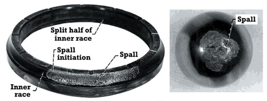
These images show representative rolling-element fatigue failure of an inner race (left)
and ball (right) from 120-millimeter-bore ball bearings made of AISI M-50 steel.
The failure manifests itself as a spall that is limited to the width of the running track and the depth of the maximum shearing stress below the contact surface. The spall can be of surface or subsurface origin. A spall originating at the surface usually begins as a crack at a surface defect or at a debris dent that propagates into a crack network to form a spall. A crack that begins at a stress riser, such as a hard inclusion below the running track in the region of the maximum shearing stress, also propagates into a crack network to form a spall.
Fatigue failures that originate below the contacting surface are referred to as classical rolling-element fatigue. Failure by classical rolling-element fatigue is analogous to death caused by old age in humans. Most bearings, however, are removed from service for other reasons.
Failures other than those caused by classical rolling-element fatigue are considered avoidable if the bearing is not overloaded and is properly designed, handled, installed and lubricated. With improved bearing manufacturing and steel processing along with advanced lubrication technology, the potential improvements in bearing life can be as much as 80 times that attainable in the late 1950s or as much as 400 times that attainable in 1940.
Basic Bearing Life
As mentioned previously, the L10 life, in millions of inner-race revolutions, is the theoretical life that 90 percent of a bearing population should equal or exceed without failure at their operating load. It is based on classical rolling-element fatigue. The “basic bearing life” often referred to in bearing manufacturers’ catalogs is the L10 life without life factors, which are dependent upon the bearing type, bearing steel, steel processing, heat treatment, lubricant and operating conditions.
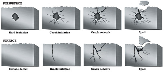
These illustrations depict a subsurface-initiated spall at a hard inclusion (top) and
a surface-initiated crack network from a surface defect.
Most bearings are selected and sized based on the “basic bearing life” calculated with and, at times, without life factors. The caveat is that on or before this calculated time, 10 percent of the bearings operating under this load and speed can be expected to fail. Many engineers do not realize that the life they have calculated is based not on the time before which no failures will occur but on the time before which 10 percent of the bearings can be expected to fail. This mistake can result in warranty and product liability claims for the equipment manufacturer.
Bearing System Life
Since it can be assumed with reasonable certainty that any rotating machinery will have two or more bearings comprising the system, you must also determine the bearing system life in addition to individual bearing life. This can be achieved by combining the individual bearing lives into a single life for the system.
To establish system life, an understanding of strict series reliability is required. Remember, the life of the bearings as a system is always equal to or less than the life of the shortest lived bearing in the system. For example, say you have a simple speed-reducer gearbox with two bearings supporting the input gear running at 3,600 rpm and an output gear supported by the same two types of bearings running at 900 rpm. At full (100-percent) load or torque, the lives of each of the input bearings are 2,500 hours, and the lives of each of the output bearings are 10,000 hours. The 10-percent life of the system would be calculated to be 1,124 hours. This means if you distributed 1,000 gearboxes and they were all operated at maximum torque for 1,124 hours, 100 gearboxes would have at least one bearing failure. The question then becomes how long could you operate the gearbox at this condition without a failure.
If the life of the shortest lived bearing in the system is 2,500 hours, it can be reasonably expected that for the first 133 hours of operation for each gearbox there will be no bearing failure. However, the gearboxes may not be operated at full output torque at all times. Assume that the gearboxes operate at full torque for 50 percent of the time, one-half torque for 30 percent of the time and one-quarter torque for 20 percent of the time. In order to calculate the total system life, you would need to calculate the L10 system life at each condition.
At an L10 system life equal to 2,671 hours, 10 percent of all the gearboxes in service would theoretically have one or more failed bearings. If, as in the previous example, you have 1,000 gearboxes in service and have 100 failed gearboxes, you would have 100 failed bearings out of the 4,000 bearings in service. In other words, 2.5 percent of the bearings in service that have failed account for 10 percent of the failed gearboxes. The other 97.5 percent of the bearings in service can reasonably be assumed to be undamaged and usable.
This is why the vast majority of undamaged bearings removed from service have never reached their calculated L10 life. Therefore, it becomes practical and cost-effective to inspect, rework and place back into service those undamaged bearings that were removed before reaching their L10 life.
Causes for Removal
So far this discussion has been based on classical rolling-element fatigue as the sole mode of failure and bearing removal. However, probably less than 5 percent of bearings are removed from service because of rolling-element fatigue, whether of subsurface or surface origin.
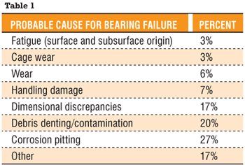
Table 1 features a list of probable causes for bearing removal and an estimated percentage related to each respective cause. In addition to this list of causes for bearing removal, related failure modes categorized under “other” would include bearing misalignment, true and false brinelling, excessive thrust/bearing overload, lubrication, heat and thermal preload, roller edge stress, cage fracture, element or ring fracture, skidding damage, and electric arc discharge.
These causes for bearing removal and failure can be minimized and/or mitigated by good bearing design, proper bearing installation, timely maintenance and good lubrication practices. However, they cannot be eliminated entirely, which makes understanding and determining bearing life even more important.
