


Figure 1. A schematic for a typical hydraulic system
An infrared camera is one of the best tools for performing regular reliability tests on a hydraulic system. It is also invaluable when troubleshooting heat, speed and pressure issues. In any hydraulic system, some lines will be at, above and below the oil temperature in the reservoir. The key is to know which lines should be cool, warm and hot. If checks are made when the system is operating normally, a reference can be established. By regularly conducting the following tests, a faulty component can be found, many times before it shuts down the machine.
A schematic for a typical hydraulic system is shown in Figure 1. The circled letters indicate the points in the system that should be shot and recorded with an infrared camera.

Figure 2. Images showing the suction and case drain temperatures
1. Check the Suction and Case Drain Lines
Check the suction and case drain lines of the pump by recording the temperatures at points “A” and “B” in Figure 1. The oil in the “A” line should be very near the oil temperature in the reservoir. The oil that flows out of the case drain line (B), is the oil that bypasses the internal components inside the pump. Most piston pumps bypass 1-3 percent of the maximum pump volume. Vane pumps may bypass as much as 5 percent of the maximum rated volume. For a 30-gallon-per-minute piston pump, the amount of oil in this line should be one-third (1 gallon per minute). Because the oil does no useful work, heat will be generated as the oil bypasses the internal pistons. This line, of course, will be hotter than the oil entering the pump through the suction line.
The suction and case drain temperatures are shown in Figure 2. The oil entering the pump is 126 degrees F, while the oil in the case drain is 135 degrees F. As the pump wears, the bypassing will increase, causing an increase in temperature of the case drain line. If the pump is checked a month later and the temperature in the case drain is 145 degrees F, then the pump has worn considerably. The flow rate should then be checked by installing a flow meter in the line. If the flow rate reaches or exceeds 10 percent of the maximum pump volume, the pump should be replaced.
In the previous example, a flow rate of 3 gallons per minute (GPM) would indicate a badly worn pump. Since the amount of case drain flow can vary from one pump manufacturer to another, the key is to make initial temperature checks when the pump is relatively new to establish a reference. Permanent installation of a flow meter in the case drain line is also recommended.
2. Check the Tank Line Temperature of the Air Bleed Valve
Check the tank line temperature of the air bleed valve at point “C” in Figure 1. The purpose of the air bleed valve is to automatically bleed air out of the line when the pump is first started. These valves are most commonly found on systems where the pump is mounted above the oil level. Once the air is bled out and the hydraulic pressure builds to the spring setting (approximately 12 pounds per square inch), the valve will shift closed. The valve is relatively small and can only handle a flow rate of 2 GPM. In most systems, the pump volume is higher than 2 GPM. Although the full pump volume usually cannot flow through the valve, heat will be generated if the valve fails open. This can increase the oil temperature as well as cause the actuators to move slower, particularly if a low-volume pump is used.

Figure 3. An air bleed valve
3. Check the Tank Line Temperature of the Relief Valve
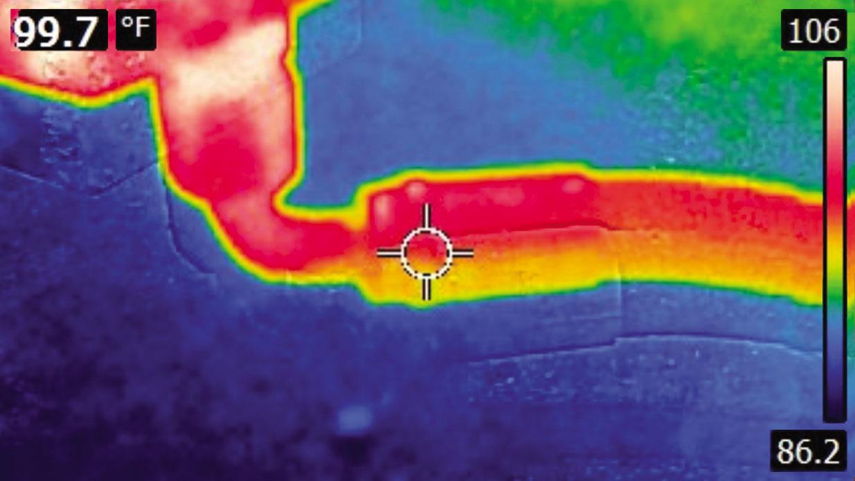
Check the tank line temperature of the relief valve (RV) at point “D” in Figure 1. In a system where a pressure-compensating pump is used, the relief valve spring should be set 250-300 pounds per square inch (PSI) above the compensator setting. The purpose of the relief valve is to provide a flow path in the event the compensator spool fails to shift and reduce the pump volume to a near 0 GPM output. The tank line of the relief valve should be at ambient temperature.
In Figure 4, the tank line is 99.7 degrees F, well below the oil temperature in the reservoir. If this line is hot, then the pump compensator spool has failed to shift, the relief valve is stuck partially open or the plant knob-turner has increased the compensator setting above the relief valve setting.

Figure 4. Image showing the tank line
temperature of a relief valve
4. Check the Tank Line Temperature of the Check Valve
A check valve (CV) is commonly used in a filtering and cooling loop, as shown on the schematic in Figure 1. The purpose of the check valve is to protect the heat exchanger from high pressure. The rating of the check valve spring is usually 65-100 PSI. If the cooler is of the air design, the internal tubes can become plugged with contamination. Also, if the unit is initially started while the oil is cold, higher resistance will be developed in the system. In either case, oil will flow through the check valve when the spring setting is reached. When operating normally, the tank line (E) should be at ambient temperature. In Figure 5, the check valve’s tank line is 142 degrees F, indicating that the cooler tubes are most likely contaminated.

Figure 5. Image showing the
tank line temperature of a check valve
5. Check the Heat Exchanger’s Inlet and Outlet Oil Temperatures
Check the inlet (F) and outlet (G) oil temperatures of the heat exchanger (HE). There should be a noticeable temperature difference between the two lines. As oil flows through the tubes of an air cooler, the heat in the oil is transferred to the air. Depending on the size of the cooler, a temperature difference of 5-10 degrees can be expected.
In Figure 6, the inlet oil temperature is shown as being 117 degrees F, while the outlet temperature is 109 degrees F, which is acceptable. If the temperature difference decreases, this may mean that the cooler fins and core are dirty or the inner tubes have become contaminated. Use caution when cleaning the fins with an air hose so no bending of the fins occurs. On water-cooled units, the temperature difference usually will be much greater, especially if chilled water is employed. The inlet and outlet water temperatures should also be recorded for future troubleshooting purposes.

Figure 6. Images showing the inlet (left) and outlet
(right) oil temperatures
6. Check the Tank Line Temperature of the Accumulator Dump Valve
Check the tank line temperature (H) of the automatic accumulator dump valve (EDV). When the system is operating, the solenoid is energized, which shifts the valve to the closed position. Flow from the main line will be blocked through the valve and back to the tank in this condition. The temperature of the line should be at or near ambient temperature. Notice in Figure 7 that the valve’s tank line is 145 degrees F, indicating that the valve is either stuck open or that the solenoid has failed.

Figure 7. Image showing the tank line temperature
of an automatic accumulator dump valve
7. Check the Temperature of the Filter’s Base and Element Housing
Often an oil filter (RF) will have an internal bypass check valve, as shown on the schematic in Figure 1. The purpose of this check valve is to provide a flow path for the oil to return to the reservoir in the event the element becomes contaminated. This prevents damage to the filter element. The temperature of the filter base should be compared to the temperature of the element housing. When the element becomes plugged, the housing will be cooler than the base. While many oil filters have visual dirt alarms to indicate the element condition, they should not be relied upon, as they have a tendency to fail over time.

Figure 8. Image showing the tank line
temperature of a manual valve
8. Check the Tank Line Temperature of the Manual Valve
Check the tank line temperature (J) of the manual valve (MDV). This valve is used as a manual accumulator dump valve. It should be opened anytime the system is shut down. This is to ensure that the pressurized fluid in the accumulator (ACC) bleeds down to 0 PSI. This provides a safety backup in the event the EDV valve were to fail closed when the system is turned off. The tank line of this valve should be near ambient temperature while operating. In Figure 8, the tank line temperature of the manual valve is 99.3 degrees F, indicating that the valve is closed.
9. Check the Temperature of the Accumulator Shell
Check the temperature at the top (K) and bottom (L) of the accumulator shell. The bottom half of the accumulator should be warmer than the top half. The heat is generated by the friction of the oil as it flows in and out of the shell. On a bladder type of accumulator, the rubber bladder will be compressed to the top part of the shell. When the pressure drops in the system, the bladder will expand and force oil out of the accumulator. If the temperatures are nearly the same, this indicates the dry nitrogen pre-charge has leaked out, the pre-charge is higher than the pump compensator setting or the bladder has ruptured. Piston accumulators will show a greater difference in heat than bladder types.

Figure 9. The bottom half of an accumulator
(left) should be warmer than the top half (right).
10. Check the Oil Temperature in the Reservoir
Finally, check the oil temperature (M) in the reservoir. A temperature gauge usually is included in the sight glass. Over time, the sight glass may become discolored, or the thermometer may fail. To obtain a consistent oil temperature reading, make a mark or draw a target on the side of the reservoir. In this manner, the oil temperature can be checked in the same location each time.
While this article has focused on temperature checks that can be made on the power supply, there often will be other pressure control, directional and manual valves located away from the power supply. Additional accumulators may also be used near the machine.
Performing these tests can help identify an issue before it becomes serious. If a shutdown of the machine does occur, the recorded information will be valuable when troubleshooting the system.
