


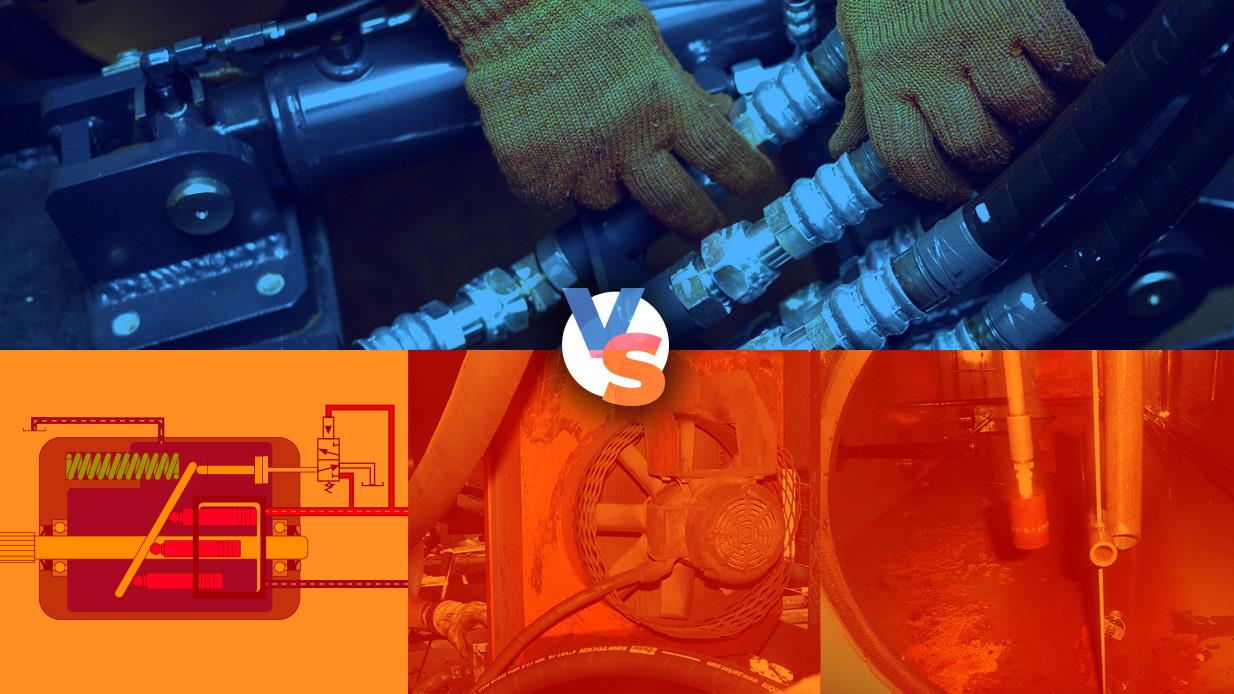

The case drain of a
variable-displacement pump
prevents pressure from building
against the shaft seal.
There is a lot to be said for reactive maintenance. “If it ain’t broke, don’t fix it!” is a common refrain across the country. In many of our hydraulic classes, the students tell us that their supervisors will not give them the time for many of the preventive maintenance techniques we teach.
Naturally, as hydraulic consultants, we advocate a more proactive routine of maintenance than what we usually find in the facilities we visit.
It’s not that we don’t understand the demands of real-world industrial settings. We understand them all too well. Our livelihood depends upon it. We know that much of a maintenance professional’s time is spent putting out fires and that preventive maintenance must be sacrificed at times in favor of continuing production.
But we also know that a machine behaving strangely is a machine that will soon transform from an asset to a liability. The trick is to know when to just leave it alone and when to intervene. There are a few times when not taking action will almost definitely result in machine failure.

A suction strainer normally
is located below the oil level.
Moving Too Slowly
When a machine moves more slowly than it used to, it’s not just tired. A reduction in speed means a reduction in flow. Either the pump isn’t delivering as much flow as it used to or the flow it delivers isn’t getting to the actuator.
Think about how a hydraulic component fails – it leaks. Either it leaks onto the floor, in which case the problem is obvious, or it leaks internally, a condition called “bypassing.” Find the bypassing component and you will find your speed problem. Ignore it and you will find yourself with lost production time.
If it’s the pump that is bypassing, it will need to be replaced. But don’t replace it right away just to “see if that will fix it.” There are some quick ways to check the pump to determine its condition. The easiest way to check an electrically driven fixed-displacement pump is to measure the current draw of the electric drive motor.
The following formula can be used to determine the horsepower required to drive a pump: Electric motor horsepower=gallons per minute x pounds per square inch x 0.00067.
This formula provides for 13 percent more horsepower than what is required hydraulically. This is necessary due to the mechanical and heat losses in the pump.
If you have a pump that supplies a volume of 30 gallons per minute (GPM) and the maximum system pressure is 3,000 pounds per square inch (PSI), the electrical horsepower can be calculated as follows:
Electric motor horsepower=30 GPM x 3,000 PSI x 0.00067, or electric motor horsepower=90,000 x 0.00067, or electric motor horsepower=60.3.
You then can check the nameplate data on the electric motor for the full load current for a 60-horsepower motor. The average full load current for a 460-volt motor is 77 amps. Therefore, if the pressure in the system is 3,000 PSI and the amperage is less than 77 amps, the pump is bypassing.
A variable-displacement pump will have a case drain that will keep pressure from building against the shaft seal. Internally bypassed oil returns to the tank through the drain instead of building case pressure. If a variable-displacement pump has excessive case flow, it is worn and must be replaced.
Piston pumps normally bypass 1-3 percent of the maximum pump volume, whereas vane pumps can bypass as much as 5 percent. By permanently installing a flow meter in the case drain line, the case flow can be measured regularly. The pump should be changed when the case drain flow reaches 10 percent of the maximum pump volume.
A monthly preventive maintenance checklist can tell you at a glance how your pump is doing. How long would it really have taken to make benchmark checks of the current draw and case flow at times when you knew the pump was good?
The pump is not the only thing that can bypass and slow down your machine. Almost all your components can bypass. This includes directional valves, cylinders, hydraulic motors, proportional valves, relief valves and other pressure-control valves.
When a component bypasses, there will be a pressure drop. As we teach in our classes, any pressure drop that doesn’t result in mechanical work will generate heat. An abnormal temperature gain across any component indicates bypassing, but there’s no way to know what is abnormal unless you already knew what was normal.
Thus, it behooves you to be familiar with your machines. An infrared temperature gun can be invaluable in learning normal temperature gains and spotting abnormal ones.

An air heat exchanger should be
located near a cool air source.
Making Strange Noises
Unusual sounds coming from a hydraulic machine shout imminent failure. If your car started making a funny noise, you would check it out or have it checked immediately, wouldn’t you? So why do you allow your expensive hydraulic machines to cry out for help as long as they are still producing? Production will halt before long if certain sounds are not addressed.
Aeration and cavitation are common indications of machine failure. Many people don’t know the difference between the two, and most will just let them continue until the pump fails and has to be replaced. But if these indicators are caught early, pump failure can be avoided.
Cavitation is a steady, high-pitched whining sound. Aeration is much more erratic and is usually accompanied by a sound similar to gravel rattling around inside a pump. Both will destroy the pump if they are not corrected right away.
The most common cause of cavitation is a plugged suction strainer or filter. Suction strainers are usually below the level of the oil, out of sight and out of mind. If cavitation is heard, check the strainer.
Low oil temperature is the second most common cause of cavitation. Never start the machine with oil colder than 40 degrees F. Also, never put it under load until the temperature is at least 70 degrees. Pump output is directly proportional to drive motor speed. If the drive motor is replaced with one that exceeds the pump’s specifications, it will cavitate and destroy itself rapidly.
Aeration results from outside air entering the pump suction. A leak in the suction line, a worn shaft seal or misaligned couplings can all cause a pump to aerate. Remember that the pressure in the pump suction is below atmospheric pressure, so oil won’t leak out, but air will leak in. A low fluid level can result in air being drawn into the pump along with the oil, so check your fluid levels.
A few years ago, I was called into a plant that had foam oozing out of a breather 30 minutes after start-up. The eventual cause was a bad coupling that wore the pump’s shaft seal. Air entered the system through the shaft seal, which eventually returned to the reservoir and purged out through the breather.

Sludge in a reservoir absorbs heat,
which can be difficult to dissipate.
Overheating
Excessive heat is the second most common cause of hydraulic failures, with the first being contaminated oil. As long as the machine is still making money, most people will allow a heat problem to continue.
But if left unchecked, an overheating machine will always result in downtime. Mineral oil begins to chemically break down at 140 degrees F. Varnish deposits develop and cause valves to stick. Viscosity drops, and the oil’s lubricating properties begin to diminish. Every component in the machine suffers as a result.
I recently was called into a plywood plant for a system that was shutting down due to a high oil temperature. The system used a 60-gallon-per-minute, variable-displacement vane pump to drive a hydraulic motor. The oil that flowed out of the hydraulic motor was ported through a heat exchanger before returning to the tank.
The system ran fine as long as the hydraulic motor was rotating, but a shutdown occurred during long idle periods. A flow meter was installed to check the case drain flow. When operating, the pressure to drive the motor was 350 PSI, and the case flow was 3 GPM. When the system was idle, the pressure built to 900 PSI at the pump outlet port.
The case flow then increased to 9 GPM. The case drain line was ported directly to the reservoir, preventing any cooling of the oil. The pump was excessively bypassing at 900 PSI, generating excessive heat.
I am always amazed that people often deal with a heat problem by adding a heat exchanger or increasing the size of the one already in place. This doesn’t solve the problem but only masks the symptom. When a machine is overheating, it is working harder than necessary.
Money is wasted by allowing the machine to overheat, and then more is wasted to cool it back down. Keep in mind that if the machine was operating fine two weeks ago and now is overheating, the problem is not a design issue. Something is wrong, and it needs to be addressed.
Increasing the capacity of the heat exchanger (or laying bags of ice on the machine, soaking it with a fire hose, opening the doors, etc.) is not the answer. Find the source of the excess heat and correct it.
There are hundreds of possible heat sources in most hydraulic machines, but a few are most common. Incorrect pressure settings cause a lot of heat problems. If a pump compensator is set higher than the relief valve, temperatures will soar.
In the absence of designer recommendations, I recommend the relief valve be set 250 PSI higher than the compensator. If the relief valve is dumping, it always needs to be investigated. Remember that relief valves in pressure-compensating pump systems only dump when something is wrong.
Pressures generally are set higher than they should be. This can be a problem with servo and proportional valve systems. Servo and proportional valves are notorious heat generators because they are seldom, if ever, all the way open.
There is always a pressure drop across them. Whenever a pressure drop occurs and no useful work is done as a result, there will be heat. The higher the pressure in the system, the greater the pressure drop across the valves and the more heat is generated.
Even if all your pressures are set correctly, the machine can overheat if it has a heat exchanger that is not properly cared for. Air heat exchangers, which are similar to a car’s radiator, should be located near a cool air source. The fins must also remain clean, i.e., you should always be able to see daylight through them. If the fins become bent, they must be straightened with a metal comb.
Sludge in a reservoir will absorb heat and make it difficult for the reservoir to dissipate it. Sludge can also enter the pump’s suction line and contaminate the entire system. Drain and clean the reservoir at least once a year or more frequently in dusty environments.
One of the best proactive measures you can take is to develop a preventive maintenance checklist for each of your hydraulic systems. By checking your systems on a regular basis, you’ll often find a failing component before it causes a shutdown of the machine.
