


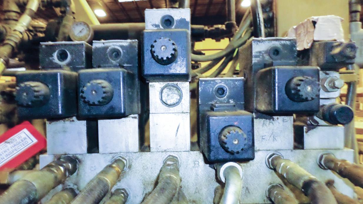
Valves located in a stack may look alike but perform completely different functions.
The philosophy at many plants is that if the hydraulic system is operating the machine, don’t mess with it. Frequently, the only hydraulic maintenance ever performed is changing the filters, checking the oil level and performing oil analysis. I recently consulted with a corrugated box plant where the return filter had not been changed since the plant started up 17 years ago.
When a hydraulic issue occurs in a plant, it normally is fixed by a parts-changing process. This is expensive in the cost of the parts and plant downtime. All maintenance personnel should have the knowledge and skills to troubleshoot and maintain in-plant systems. The following are four things every hydraulic troubleshooter needs to know.
1. The Function of the Components
When a hydraulic problem occurs, the machine is visually inspected for busted hoses, pressure on the gauge, low oil level and if the electric motor is tripped out. If nothing obvious is found, a parts-changing process begins. Guess which component is usually changed first? If you said the hydraulic pump, you’d be right.
One of the biggest misconceptions is that a pump supplies pressure. Pumps deliver volume or flow. Pressure is only created when there is resistance in the system. Many a good pump has been changed because the gauge showed little or no pressure. This is a perfect example of the hydraulic troubleshooter not knowing the function of the pump in the system.
Before any troubleshooting begins, maintenance personnel should understand the function of all the system’s components. They can’t always be identified simply by looking at them. One valve may look like another but perform an entirely different function.
Many valves have a symbol on the housing tag to indicate the type. This is the easiest way to distinguish valves, but it is of no use if the maintenance person isn’t familiar with hydraulic symbols.
2. Troubleshooting Procedures
A hydraulic troubleshooter must know the proper procedure for verifying whether a component is good or faulty. In most cases, a quick check or test can be performed.
Accumulators are commonly used to supply additional volume, absorb shock and maintain pressure in the system. They typically are pre-charged with dry nitrogen.
For the accumulator to perform appropriately, the nitrogen pre-charge must be correct. There are three easy methods to verify whether an accumulator is operating properly.
The first method is to turn off the hydraulic pump and allow the pressure to bleed down to 0 pounds per square inch (psi). Install a charging rig with a gauge on the accumulator’s Schrader valve. The nitrogen pre-charge will be indicated on the gauge.
Another method is to watch the pressure gauge as nitrogen forces oil out of the accumulator shell when the pump is turned off. The pressure will gradually fall and then rapidly drop to 0 psi. The pressure at which the needle quickly drops to 0 is the pre-charge pressure.
The final method is to shoot the sides of the accumulator shell with a temperature gun or infrared camera. The shell should be warmer in the lower half or two-thirds when the pre-charge is correct.
I recently consulted with a plant where several accumulators were found to be undercharged. When an accumulator is undercharged, less volume is delivered to the system. Once properly charged, the machine’s line speed was increased to reach a higher level of production. These pump and accumulator examples are indicative of the quick tests that can be made to determine whether a component is operating correctly.

A charging rig with a gauge can be installed on
an accumulator’s Schrader valve.
3. How to Adjust the System
One of the main problems, if not the biggest problem, is that random adjustments are made on a system in an attempt to speed up the machine or fix a problem. Often, an adjustment is made, but if no change in machine operation is seen, it is assumed that nothing has changed in the system.
At one plant, the local “knob turner” thought a hydraulic pump was too noisy, so he turned the compensator adjustment clockwise and cracked open a manual valve in the line immediately downstream. The pump’s noise level dropped somewhat, so he left, thinking he had solved the problem.
Several hours later, the machine shut down because the oil temperature had risen to 160 degrees F. An electrician was called, who promptly jumpered out the high-temperature shutdown switch. Some 24 hours later, the oil temperature rose to 300 degrees F. The machine then had to be shut down and flushed with an expensive solvent to remove varnish and sludge from the system.
By rotating the compensator clockwise, the knob turner set the compensator above the relief valve’s setting. This enabled the pump volume to return to the tank at a high pressure, generating heat when not required in the system. Opening the manual valve allowed some of the pump’s volume to return to the tank at all times under high pressure, generating even more heat.
All maintenance personnel must be trained to precisely set pump compensators, relief valves, flow controls, pressure-reducing valves and pre-charging accumulators. If this is not done, shock, leakage, overheating, component failure and damage to the machine can result.

A commonly used directional valve

The hydraulic symbol for a directional valve
4. How to Read Hydraulic Symbols
A schematic should be used to effectively troubleshoot a hydraulic problem. Therefore, maintenance personnel must know how to read hydraulic symbols in order to troubleshoot from the schematic.
A commonly used directional valve is shown on the left along with the symbol for the valve. This symbol indicates five things about the valve: it is normally open (with a pipe plug in the “A” port), has two positions, is four-way, is solenoid-controlled and hydraulic-piloted, and has a spring return.
Without reading the symbol, the only thing that might be identified by looking at the valve is that it is solenoid-controlled. Not knowing the valve’s five attributes would make troubleshooting much more difficult.
A valve often is installed on a machine simply because it looks the same as the original valve. If even one letter or number is different, it must be discovered before the valve is changed. When one plant replaced a valve that had a single number difference between the original and the new valve, it resulted in eight hours of downtime at a cost of $12,000 per hour.
If your maintenance crew is not trained on these four things, they likely will do the best they can when an issue occurs, which usually means changing parts until the problem is solved. Frequently, many parts are changed and the machine is fixed, but no one learns anything.
By properly training your maintenance personnel, you will spend less on equipment parts, reduce your hydraulic-related downtime and enjoy a safer workforce.
