


Contamination is the cause of approximately 90 percent of all hydraulic system failures.
If you can maintain desired cleanliness level and keep oil temperature-controlled, then downtime can be kept to a minimum. The ideal oil temperature for an industrial hydraulic system is 120 F.
If the temperature reaches 140 F, oil begins to break down. The life of the hydraulic oil will be cut in half for every rise in temperature of 15 F above 140 F.
Mobile hydraulic systems generally are designed to operate at higher temperatures due to their smaller reservoir size, which limits the amount of heat that can be dissipated to the atmosphere through reservoir walls.
A higher viscosity oil is often used in mobile systems in order to operate at higher temperatures.
Contaminant particles in hydraulic systems are measured in microns. One micron is one-millionth of a meter. The clearances inside most pumps and valves are approximately 0.0004 inches.
How small is this? Consider that a grain of salt is 0.0039 inches or 100 microns. The lower visibility of the human eye is 40 microns (0.00158 inches).
A red blood cell is 0.0003 inches or 8 microns. A particle much smaller than what the human eye can see is capable of causing a hydraulic system failure.
Hydraulic filters should be selected to protect the most critical components in the hydraulic system.
In the “old days,” a 10-micron filter was used to protect a system without servo valves, but there was no measurement for how efficient the 10-micron filter was. Did it remove all particles that were 10 microns and above, or only some of them?

A desiccant breather can
be used to remove moisture
from the air before it
enters the tank.
Today, filters are assigned a beta rating to determine their efficiency.
The beta rating represents the number of particles that enter the filter relative to the number of particles that are flowing out. System filters should have a beta rating of 75 or higher.
For a 10-micron filter, this is expressed as B10=75. This means that for every 75 solid, spherical particles (10 microns and above) entering the filter, only one particle will exit the outlet port. Beta ratings of 200 are common for many filters in use today.
Contamination levels in hydraulic systems are measured by the ISO 4406 cleanliness code. The desired target level is dependent on the most critical hydraulic component and the pressure in the system.
This is expressed in three numbers, which represent the number of contaminants that are 4, 6 and 14 microns and above in a 1-milliliter oil sample. For example, if a variable piston pump is the most critical system component and the maximum system pressure is 1,500 pounds per square inch (psi), then the target level would be 18/16/13. A 5-micron filter is necessary to achieve this target level.
If the same pump is used in a system that operates at 2,500 psi, then the target level would be 17/15/12. More metal breakdown occurs at higher system pressures. One or more 3-micron filters would be required to meet this target level.
If the oil sample for the 1,500 psi system indicates a 20/18/12 level, then the system is not being maintained to the desired standard of 18/16/13.
This may be due to the filters not having the proper beta rating or the existing system filters being contaminated and allowing oil to flow through the internal bypass check valves (if used).
Once the desired cleanliness level has been identified, the next step is to determine where the filters should be located. Consider the following seven system locations where contaminants can be removed.
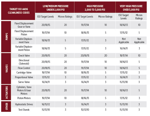
These target ISO 4406 codes indicate the required
cleanliness levels for various system components.
Reservoir Breather
Whenever the oil level drops in a reservoir, atmospheric air will flow through the breather. Many hydraulic units contain an inexpensive breather that doubles as a fill cap, but oil should never be added to the system without being filtered.
Not only is it important to remove solid contaminants from the air but also to keep moisture out of the tank. Air contains water vapor, which can turn into liquid moisture once it cools down inside the tank.
A desiccant breather can be used to remove the moisture from the air before it enters the tank. Through the use of an adapter, this type of breather can be mounted on the same base as the existing, old-style breather.
The desiccant crystals will change color as the moisture is absorbed. Most desiccant breathers contain a 3-micron internal filter for removing solid particles from the air. Your selected breather should also have a visual dirt alarm to indicate the condition of the particulate filter.
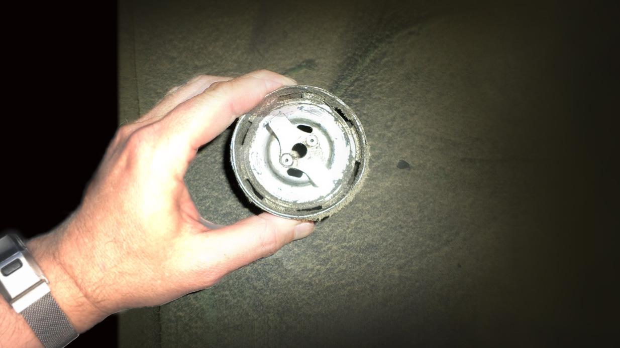
Pump Suction Filter
The purpose of a suction filter is to prevent large particles from entering the pump. This filter may be in the form of a strainer located underneath the fluid level. These strainers usually have a 74- or 149-micron rating.
I recently consulted with a corrugated box manufacturer which had changed several pumps on one particular system during the past year.
When the reservoir was drained and the suction strainer inspected, a large split was found down the center of the screen. When I asked how long it had been since the strainer was changed or cleaned, the maintenance mechanic said, “Never in the 17 years I’ve been at the plant.”
Suction strainers should be removed from the reservoir at least twice per year and cleaned or changed. Often there will be a suction filter access flange located where the pump suction line enters the reservoir. This permits the removal of the strainer without draining all the oil from the tank.
A better method of cleaning the fluid to the pump’s suction port is to mount an external filter in the line. This filter should also have a visual indicator to monitor the condition of the element.
Filters often are connected in the return lines
of a system’s directional valves.
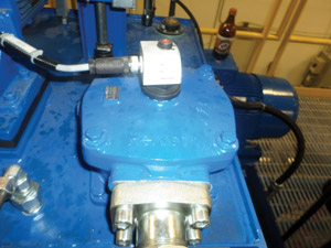
Pressure Line Filters
As pumps operate, metal breakdown occurs. When the pressure exceeds 2,200 psi in a system with a fixed displacement pump, a pressure filter should be mounted in the pump outlet line.
This will filter the metal particles prior to being directed to the system. When a variable displacement pump is used at pressures higher than 1,500 psi, a filter should be installed in the pressure line.
The best method of monitoring the element condition is through the use of a pressure switch. Once the element becomes partially contaminated and the pressure drop across the element reaches the switch setting, an electrical signal will be sent indicating the condition.
The switch may be used to provide an alarm on the operator’s screen that the filter is nearly contaminated. Most pressure filters contain an internal bypass check valve to allow the oil to flow continually to the system once the element is contaminated.
The rating of the check valve spring is usually 7-10 psi higher than the setting of the pressure switch. The best method of filtering is to install a dual filter system where one element is active and the other is a standby. When the pressure switch indicates the online element is contaminated, the clean filter can be selected without shutting down the system.
Pressure filters are also commonly used immediately upstream of proportional valves and servo valves. This is due to the extremely tight clearances inside the valves. The majority of these filters are of the non-bypassing type.
The filter should be mounted as close as possible to the valve. It is imperative to change these filters on a regular basis to prevent collapsing of the element, resulting in a catastrophic failure of the valve.
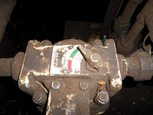
Visual indicators can fail and
should not be relied upon.
Return Line Filters
Filters are often connected in the return lines of a system’s directional valves. This allows the oil that exhausts out of the cylinders and motors to be filtered before returning to the reservoir.
However, this type of filtration is only effective if at least 20 percent of the system volume is ported through the element in one minute. For example, with a pump volume of 100 gallons per minute (GPM), a minimum of 20 GPM should flow through the return filter. Many systems, such as reject kickers, only operate sporadically, rendering the return line filter ineffective.
Visual indicators and pressure switches can be used to monitor the element’s condition. The issue with visual indicators is that they can fail and therefore should not be relied upon.
A filter maintenance schedule can be established by initially sampling the oil for several weeks or months. I once consulted with a plant in Oregon that changed the large return filter on its press every month. After the oil was sampled monthly, it was discovered that the ISO cleanliness code was only exceeded after eight months. The plant then scheduled the element to be changed every six months.
Case Drain Filters
Any oil that bypasses a variable displacement pump or an externally drained hydraulic motor will flow through the case drain line and into the tank.
The oil that bypasses will contain contaminants generated by the metal breakdown in the pump and motor. A small filter can be installed in the case drain line to remove the contaminants. Prior to installing these filters, the rating of the pump or motor shaft seal should be checked.
For most variable displacement pumps, the shaft seal rating is 10-15 psi. Hydraulic motor shaft seals usually have a higher rating (approximately 50 psi). An internal or external check valve should also be used to allow the oil to bypass when the element becomes contaminated.
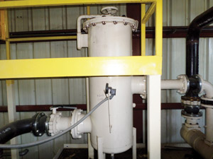
Kidney-loop system filters may be quite large.
Kidney-loop System
A kidney-loop system consists of a separate pump and filter. Frequently, a heat exchanger is also connected in the loop. The pump constantly recirculates the oil in the reservoir through the filter and cooler.
These filters can be quite large. The reservoir volume should be turned over five to seven times in one minute by the recirculating pump. For example, if the reservoir holds 3,000 gallons, to filter the oil five times (15,000 gallons) in one minute, a 250 GPM pump will be required.
Gear-type pumps are recommended due to their ability to withstand contaminants better than vane or piston pumps. A visual indicator should be used to monitor the filter’s condition.
There is no magic rule of thumb for the number and type of filters that should be used in a system. Can you have too many filters in a system? No, but the more that exist, the more time will be required to maintain them.
Often it is assumed that the filter on a machine is working when in reality, oil is flowing through the bypass check valve.
If one or more systems in your plant are not meeting the recommended ISO cleanliness level, examine the system to ensure the filters are in the proper locations. Also, verify that the filters are changed on a regularly scheduled basis.
This can be established through oil analysis. By keeping the oil in your hydraulic systems clean and cool, hydraulic downtime will be kept at a minimum.
Spin-On Filters

Spin-on filters are often used on return line low-pressure applications as well as some pump suction applications. They're commonly found in mobile equipment such as compactors, mowers, tow trucks, trenchers, cranes, and truck-mounted aerial lifts. The efficiency of a spin-on filter depends on the media type. Most come in a variety of materials, including cellulose, fiberglass, or wire mesh elements with pressure ranges up to 250 PSI. Multi-layered, non-woven glass media provides the highest levels of depth filtration efficiency and capacity, making it the ideal filter to achieve longer equipment life.
