


Situation
The client Proalco requested a visit from Compañía de Lubricantes to evaluate the reasons why one of the gearbox lubricants operating in the drawing section presented a degradation to the point that the oil solidified and jammed the reducer during a morning start-up.
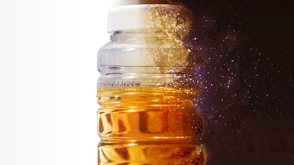
Below is the lubricant condition found by Proalco's maintenance team; see image 1.

Lubrication Evaluation
Because it was not possible to extract enough volume to perform an oil analysis on the degraded lubricant, it was decided to perform the following actions:
- Take a sample of lubricant in equipment with an hour meter similar to the one that presented the failure.
- Perform thermographic analysis of the equipment that presented the failure.
- Take a sample of the lubricant that the gearbox had on the day of the visit (new lubricant).
The results of the tests carried out will be presented below.
1. Take a Sample of Lubricant in Equipment with an Hour Meter Similar to the One that Presented the Failure
The oil analysis was performed on the equipment that experienced weather conditions similar to those that presented the failure. Due to its operating conditions, this equipment's lubrication is based on top-ups and does not have a set frequency for oil changes.
Due to extended changeover times, these characteristics generate stronger operating environments, as lubricant fillers only mitigate the oil's natural degradation conditions but do not regenerate it.
These analyses are based on the SACODE criterion of health (SAlud), Wear (DEsgaste), and Contamination (COntaminación).


Image 2 shows how health, contamination, and wear results are on alert.
Regarding the health of the lubricant, it is evident that the viscosity could not be measured due to the high water content in the lubricant. The water and other solid contaminants cause the lubricant to present oxides and much more aggressive compounds that cause accelerated degradation.
The contamination results, see Image 3, show that not only is the lubricant contaminated with water, but it also presents contamination with silicon. This may be due to dirt entering the reducer due aluminum evidence as dirt contains silicon and alumina at a ratio of about 4:1, and the remaining concentration of silicon may be due to seals detaching or seizing.
The oil analysis finds calcium at more than 3,100 ppm, indicating contamination in the oil from a calcium-based grease.
Contamination of an oil lubricant with calcium-based grease results in the uncontrolled formation of a semi-solid/ solid lubricant. Therefore, the formation of semi-solid/ solid masses, as shown in Image 1, extracted from the affected reducer, is a product of a chemical reaction between the lubricant and mix of contaminants.
The chemical and physical reactions between the oil and the contaminants ( including water, soil, and calcium thickener grease) generate an alteration in the lubricating film that works on the components of the reducer, resulting in metal-to-metal contact and a lack of surface protection, which can be seen in Image 4, where the presence of metals such as copper and tin represent the wear of the bronze crown. In contrast, the levels of iron (Fe) and the high ferrous density index (PQ Index) represent possible wear of the worm shaft and bearings.
It should be noted that in this type of gearbox, the presence of a high PQ provides information about the critically advanced wear of ferrous components in contact with the softer metals since these metals. Consequently, wear begins and is more advanced with these types of metals.
2. Perform Thermographic Analysis of the Equipment that Presented Failure
In the thermography carried out, the thermal conditions of the power transmission system were evaluated, specifically:
- Electric motor
- Electric Motor Shaft – Transmission pulleys
- Shaft Drive pulleys – Housing Internal worm shaft bearing
- Auger gearbox – Housing external worm shaft bearing

The operating conditions of the motor evaluated in the equipment housing show that, on average, the equipment is operating at 43.3°C, which is a normal and stable value for the motor. The axis at the motor outlet towards the pole is valued higher than 47.3°C, which will be shown in the following image.

The electric motor shaft that reaches the transmission pulley has operating temperatures of 50.2°C, which is within normal values for electric motor output shafts. The temperature delta between the housing and motor shaft does not exceed 10°C, which is a normal operating temperature delta.

The temperature of the shaft entering the worm reducer is 66.4°C, and the temperature of the bearing house is 64.4°C. These values are within operating ranges for worm gear reducers, however, the bearing track outside the housing presents temperatures of 83°C. This is due to the mechanical installation, which can cause bearing alignment and lubrication problems.

The thermography shows there is not expected thermal uniformity in the reducer; on the contrary, there is a temperature delta between the right and left ends of the reducer. This 6°C temperature different indicates an anomalous condition at the right end of the reducer. It can be seen how this housing condition is higher than 71°C, which will be reviewed in detail below.

The thermography in Image 13 shows outer bearing housing temperatures of 89.9°C. Due to heat transfer, this indicates the bearing would be working between 90°C and 100°C. This is above the recommended operational value for compound mineral oils; after 75°C-80°C, these lubricants begin to exponentially degrade (every 10°C change in temperature represents a decrease in its useful life by 50%). The inspection was also carried out on additional outer bearing housings on the same line, and two more presented housing temperatures of 90°C-110°C.
3. Take a Sample of the Lubricant that the gearbox Had on the Day of the Visit (New Lubricant)
This analysis was carried out on the equipment that presented the failure due to the "hardening" of the lubricant seen in Image 1. Since extracting the minimum volume of oil to analyze this hardened lubricant was impossible, a sample was taken from the new oil (less than one month of use) currently in the gearbox. Below, in Images 15, 16, and 17, you will find the results.


In Image 15, the lubricant has an oxidation level of 15 Ab/cm, which indicates an oxidation stage that has already started and is accelerated by the operating time. The reasons this oxidation occurs in such a short time are twofold.
First, operating conditions, such as bearing and reducer temperatures, exceed 80°C, which, as discussed above, exponentially reduces the lubricant's useful life. Second, the conditions under which the new lubricant was applied may have been subjected to remnants of the previous lubricant, which catalyzes the degradation of the new oil.
This equipment also presents values of calcium, although lower than those present in Images 2, 3, and 4. As explained in point 1, this contamination is due to the grease the facility used, which is cross contaminating the new lubricant. This will produce a physical and chemical degradation of the oil, turning it into a semi-solid/ solid that will not lubricate any of the reducer’s components.
Conclusions
- The formation of the semi-solid/ solid paste found in the crown auger of the B.A.C.A 11 #2 drawing machine (Images 2, 3, and 4) is due to contamination by calcium soap from the lubricant used in the production process.
- The gearbox bearings' temperatures are above 90°C, accelerating the degradation of the lubricant and exponentially increasing the component’s wear rate.
- A high level of water was found in the reducer of the B.A10 drawing machine (Images 2, 3, and 4). Calcium contamination and high operating temperatures solidify the lubricant, mechanically compromising the equipment.
Recommendations
- Remove the entry points of the solid lubricant and water into the gearbox.
- Verify the bearings' operating conditions to eliminate temperature increases; this may be in installation, selection, or correct lubrication.
- Establish frequencies for changing lubricants, either under preventive or predictive frequencies.
This case study and imagery were originally submitted in Spanish but have been translated into English specifically for publication in Machinery Lubrication.
